
DSRC
A Promising Technology
Making roads a safer place for drivers - this was the promise of Dedicated Short Range Communications (DSRC). Originally released in the early 2000s, this new communications protocol was an extremely promising new technology. DSRC promised the possibility of all cars on the road having the ability to communicate with one another. So what does this mean? Imagine a traffic jam up ahead further than your eye can see. Imagine that the cars currently sitting in the traffic jam were able to communicate the congestion to the approaching cars, potentially saving accidents from happening. If cars on the road were able to communicate with each other and listen for safety-related broadcasts from other DSRC enabled devices, then surely we were on our way to a breakthrough in safe driving technology.
But more than 20 years after its creation, we still have not seen this technology fully realized. The cause of this is for numerous reasons, but one of the main sticking points is how interpretations of the DSRC standard have been inconsistent. When a manufacturer builds new equipment, it can sometimes speak a slightly different dialect than others. This causes concern with municipalities looking to DSRC as a way to achieve huge gains in the safety of their roads. Often, they find it's not worth the investment when they cannot guarantee that this equipment can be effective without a costly rollout. Furthermore, when safety is at stake, they cannot afford to work out issues in DSRC communication on real roads.
The Details
To understand why DSRC devices made by different manufacturers have a hard time communicating with one another, it's important to know some of the building blocks of the technology. The DSRC environment consists of three main components: an on board unit (OBU1), a roadside unit (RSU2) and the messages that are sent between each of these. These vehicle-to-vehicle and vehicle-to-infrastructure messages are defined by DSRC ISO specifications (J27353 and J29454). The purpose of this specification is to provide the information exchange between a host vehicle and another DSRC enabled device to address safety and mobility concerns. Some examples of messages include Signal Phase and Timing (SPaT), Map Data (MAP), Basic Service Messages (BSM), and Traveler Information Messages (TIM). 5
DSRC Equipment manufactured by hardware companies can interpret these specifications in a different way. This difference in interpretation can have negative consequences on the safe and reliable deployment of DSRC equipment within municipalities. Having different interpretations of the specification can cause equipment from different manufacturers to, in essence, speak different languages. And, in order for this infrastructure to be successful, all manufacturers equipment should be able to speak to each other effectively.
Proposed Solution
In order for municipalities to deploy DSRC equipment safely and reliably, an automated system can be created for DSRC scenario based testing. This system can run through thousands of test scenarios in a lab setting before real devices are installed in vehicles and on streets. This can greatly reduce the cost of deployments.
This goal can be achieved by:
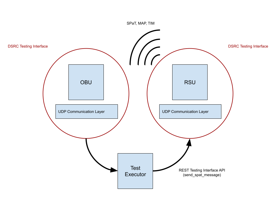
Defining new interface to enable test automation for DSRC equipment (see DSRC Testing Interface in Figure 1)
Creation of an OBU application providing an implementation of this testing interface
Off-board application that provides a communication interface for testing with the RSU
Using these components will allow the user to set up messaging scenarios and verify expected behavior. Additionally, it enables the creation of a suite of automated tests that can be reused and evolved to run against a target device. The test interfaces provide a language agnostic method of communicating with DSRC equipment as well as increasing productivity for the teams creating new test scenarios.
This test framework would enable the creation of SPaT, MAP, TIM and BSM messages, and allow the user to see these messages as they flow through the system.
Features of the DSRC Testing Framework
For this system to be effective, it must allow its user to easily build up these DSRC messages, send them through the DSRC system, and read results to ensure that they look correct on the other side.
SPaT, MAP, TIM and BSM messages are defined by ISO J2735. This specification provides ASN.16 definitions of the structure of these messages. ASN.1 definitions provide a standard method for describing the information contained in a DSRC method, and also provides a great opportunity to automatically convert programming language data structures into these encoded forms so that they can be sent across the air.
Once the messages are received by the second device, we can use the same translation mechanism to convert those DSRC messages back to a programming language data structure for comparison by a testing framework.
Consider a real example of this process: a test describes a SPaT message stating that a yellow light up ahead is about to turn red, a RSU transmits this message automatically, an OBU picks up the broadcasted message and interprets it, and then our test framework verifies that the message made it on time and with the correct content.
Some other useful features of this testing framework include:
Sending and receiving log files from RSU and OBU devices
Test suites that can be used with any continuous integration system
An extensible architecture
Ability to create new tests based on ISO J2735 and J2945 DSRC scenarios
Easily update ASN.1 message properties as specs change
Easy addition of 3rd party equipment (i.e. traffic controllers)
A framework for sending predictable messages for development of OBU applications
This system would allow for testing of all components of DSRC, and in any direction desired. These are usually denoted as:
V2V (OBU to OBU)7
V2X (OBU to RSU)8
V2I (RSU to OBU)9
Figure 1 shows the V2I testing scenario.
References and Further Reading
OBU: “An OBU is a transceiver that is normally mounted in or on a vehicle, or in some instances may be a portable unit.” - FCC.gov
RSU: “An RSUs is a transceiver that is mounted along a road or pedestrian passageway. An RSU may also be mounted on a vehicle or hand carried, but it may only operate when the vehicle or hand-carried unit is stationary. An RSU broadcasts data to OBUs or exchanges data with OBUs in its communications zone.” - FCC.gov
J2735: “This SAE Standard specifies a message set, and its data frames and data elements specifically for use by applications intended to utilize the 5.9 GHz Dedicated Short Range Communications for Wireless Access in Vehicular Environments communications systems.” - SAE.org
J2945: “information exchange between a host vehicle and another DSRC enabled device, a device worn by or otherwise attached to a traveler, a roadside device, or a management center, to address safety, mobility, and environmental system needs.” - SAE.org
More information on SPaT, MAP, BSM, and TIM message types - SNIP Knowledge Base
ASN.1: “a formal notation used for describing data transmitted by telecommunications protocols, regardless of language implementation and physical representation of these data, whatever the application, whether complex or very simple.” - ITU.int
V2V: “Vehicle-to-vehicle (V2V) communication enables vehicles to wirelessly exchange information about their speed, location, and heading.” - NHTSA.gov
V2X: “vehicle-to-vehicle (V2V), vehicle-to-infrastructure (V2I), and vehicle-to-pedestrian (V2P) communications, collectively known as “V2X.”” - Transportation.gov
V2I: “[vehicle-to-infrastructure (V2I)] technologies capture vehicle-generated traffic data, wirelessly providing information such as advisories from the infrastructure to the vehicle that inform the driver of safety, mobility, or environment-related conditions.” - its.dot.gov
FCC Modernizes 5.9 GHz Band to Improve Wi-Fi and Automotive Safety
Vehicle to Vehicle Communication Technology for Light Vehicles
Figure 1: DSRC Testing Framework
The Future of Vehicle to Vehicle Communication
During the period of time that research was being conducted for this case study, the FCC reallocated all of DSRC's spectrum for other uses due to lack of adoption 10 . These spectrums are now allocated in part to Cellular V2X communications.
Although this change may make it seem that the future of DSRC is grim, some continue to push for a standardization of vehicle to vehicle communications. To ensure the reliability of these systems in the future, an automated testing framework like the one described in this case study will be needed to ensure that the next generation of DSRC doesn't suffer a similar fate.